![]()
RVT_ELEC_01101 Free Certification Exam Material from VCETorrent with 65 Questions
Use Real RVT_ELEC_01101 - 100% Cover Real Exam Questions
Autodesk RVT_ELEC_01101 Exam Syllabus Topics:
| Topic | Details |
|---|---|
| Topic 1 |
|
| Topic 2 |
|
| Topic 3 |
|
| Topic 4 |
|
| Topic 5 |
|
NEW QUESTION # 18
Refer to exhibit.
A portion of an electrical fixture family's Type Properties is shown in the exhibit.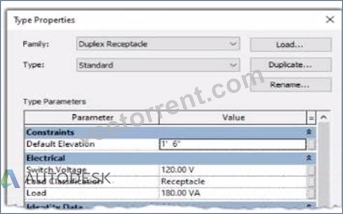
Because of the value of the Type Parameter Load Classification, an electrical designer expects the fixture's Load Classification to display as -Receptacle" when circuited. Instead, it displays as "Other".
What should the designer do to make the circuited fixture's Load Classification always match the family's Type Parameter?
- A. Edit the family. Change the power connector's Load Classification to "Receptacle". Reload the family into the project.
- B. Edit the family. Delete the power connector and place a new power connector. Parameter associations will be made automatically. Reload the family into the project.
- C. Edit the family. Associate the power connector's Load Classification with the family parameter. Reload the family into the project.
- D. Edit the fixture Instance in the System Browser. In the Load Classification column, associate the fixture's Load Classification to the family parameter.
Answer: C
Explanation:
In Autodesk Revit Electrical Design, each electrical family (such as a receptacle, lighting fixture, or equipment) can contain one or more connectors that define how it interacts with the electrical system. The Load Classification parameter determines how the connected load is categorized in electrical schedules and load calculations (e.g., Lighting, Power, Receptacle, Other).
When a family's Type Parameter Load Classification does not display correctly (e.g., it shows "Other" instead of "Receptacle" after being circuited), the issue lies in the power connector's internal parameter not being linked to the family-level "Load Classification" parameter. Revit uses the connector's classification to determine the load type when it is connected to a circuit - if the connector isn't associated, the classification defaults to "Other." According to the Autodesk Revit MEP User's Guide (Chapter: Electrical Systems - Creating Electrical Families), it specifies:
"To control how a component reports its connected load type, associate the power connector's Load Classification parameter with a corresponding Family Parameter. This ensures the load classification in the circuit matches the family definition, rather than defaulting to 'Other.' To correct existing families, edit the family in Family Editor, select the connector, and associate its Load Classification parameter with the family's Load Classification type parameter. Then reload the family into the project." This confirms that the correct approach is to edit the family and create or link the Load Classification parameter to the connector's Load Classification field. Merely changing the connector value (option C) won't ensure dynamic synchronization between the family type and circuit. Deleting and re-adding the connector (option B) won't automatically create that link. Option D (editing through the System Browser) modifies instance-level data, not family associations.
Hence, the correct and permanent fix is:
Open the family in the Family Editor.
Select the power connector.
In the Properties palette, click the small Associate Family Parameter button () next to Load Classification.
Link it to the family's Load Classification parameter.
Save and reload the family into the project.
References:
Autodesk Revit MEP 2011 User's Guide, Chapter 53: Creating Electrical Families, pp. 1254-1257.
Smithsonian Facilities Revit Template User's Guide (2021), Section 8.3. Electrical Design: Power Connector Parameters.
Autodesk Revit 2020 Help: "Associate a Connector Parameter with a Family Parameter."
NEW QUESTION # 19
Refer to exhibit.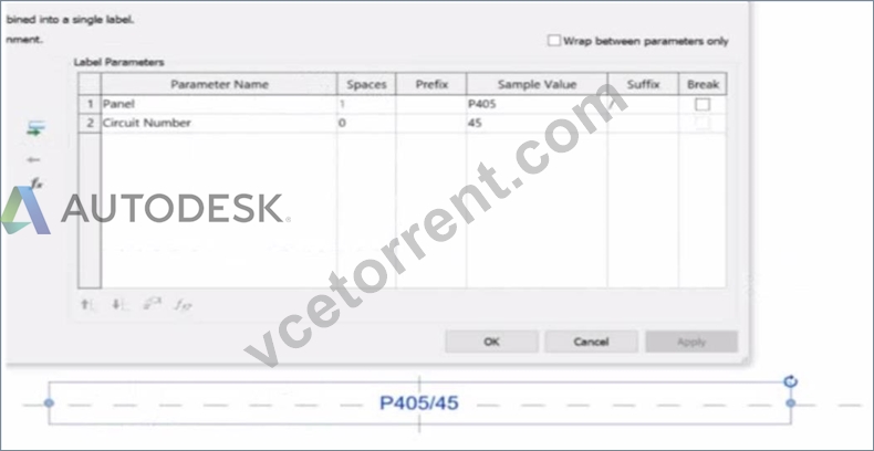
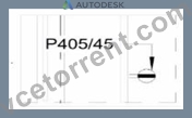
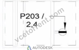
An electrical designer is working on an Electrical Device Panel-Circuit tag. The designer tags a receptacle using the tag properties shown in the exhibit The receptacle is assigned to panel P203 and circuit 2.4.
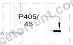
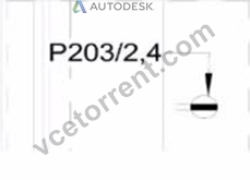
Which option shows the correct tag?
- A.
- B.
- C.
- D.
Answer: C
Explanation:
In the exhibit, the Label Parameters for the electrical device tag are configured as follows: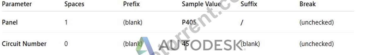
This setup determines how the tag will display in Revit when applied to any device. Specifically:
The Panel parameter (P203 in this case) will be shown first.
A "/" separator follows because it's assigned as the suffix for the Panel parameter.
The Circuit Number (2,4) is displayed immediately after the slash, with no extra spaces or line breaks.
Since the Break column is unchecked, the values will appear on one continuous line, not split across lines.
Revit documentation for tag creation confirms this behavior:
"When defining label parameters in a tag family, the Prefix and Suffix fields control text that appears before or after the parameter value, while the Break checkbox controls whether the text wraps to a new line." Therefore, when the tag is applied to a receptacle on panel P203 and circuit 2,4, the final formatted text will be:
P203/2,4
This corresponds exactly to option B, where the panel and circuit appear on the same line separated by a slash, with no spaces or line breaks.
NEW QUESTION # 20
Refer to exhibit.
In this linked architectural model, demolished walls are missing The electrical designer teams from the architect that the walls have been placed in a phase that does not exist in the host model.
Which steps should the designer lake to associate the architectural phases to their phases?
- A. Open Manage Links > Manage Phases
- B. Select the link > Edit Type > Phase Mapping
- C. Open Visibility Graphics > Revit Links > Display Settings
- D. Select Phases > Graphic Overrides
Answer: B
Explanation:
In Autodesk Revit, when demolished walls or other elements from a linked architectural model are missing in the host model, the issue typically lies in phase inconsistency between the host and linked models. The architectural model may include elements created or demolished in phases that do not exist or are mismatched in the electrical model (the host). To resolve this, Revit allows users to map phases between the host and linked models through the Phase Mapping tool in the link's Type Properties dialog.
According to the Autodesk Revit MEP Electrical Design Guide (Linked Models Section, pp. 1282-1287), the official procedure is:
"You can manually set up a correspondence between phases in the host model and phases in the linked model. To do this, you set up a phase map in the properties of the linked model, and then apply the phase map in the host model." (Revit MEP User's Guide, Chapter 53 - Linked Models, p. 1282) The step-by-step process is precisely described in the Revit documentation as follows:
To map phases in the linked model:
In the drawing area of the host model, select the linked Revit model.
Click Modify | RVT Links tab ➤ Properties panel ➤ Type Properties.
In the Type Properties dialog, find the Phase Mapping parameter and click Edit.
In the Phases dialog, select the appropriate mapping options for each phase, and click OK.
Click OK to exit the Type Properties dialog.
(Revit MEP User's Guide, p. 1287)
This procedure ensures that demolished or existing architectural elements display correctly according to the electrical model's phase structure. Without this mapping, Revit cannot interpret which linked phase corresponds to the host's "Existing" or "New Construction" phases, causing certain geometry-like demolished walls-to disappear from view.
Supporting Extracts from Revit for Electrical Design Study Documentation:
Linked Model Type Properties:
"To modify the type properties of a linked model, select the linked model in the drawing area, and click Modify | RVT Links tab ➤ Properties panel ➤ (Type Properties).
The Phase Mapping parameter allows you to set up a correspondence between phases in the host model and phases in the linked model." (Revit MEP 2011 User's Guide, p. 1305) Phases and Linked Models Concept:
"When you link a Revit model that has more than one phase, phases in the host model automatically map to phases in the linked model. When this initial mapping occurs, Revit maps phases by matching phase names.
You can manually set up a correspondence between phases in the host model and phases in the linked model using the Phase Mapping function." (Revit MEP 2011 User's Guide, p. 1282) Phase-Specific Room and Element Display:
"If phase-specific elements in a linked model do not reflect correctly, check phase mapping for the linked model. If automatic mapping does not give the desired result, map phases manually between projects." (Revit MEP 2011 User's Guide, p. 710) Conclusion:
Therefore, to fix the issue where demolished walls are missing in a linked architectural model, the electrical designer must perform manual phase mapping between the architectural model and the host electrical model. This is done by selecting the linked file, opening its Type Properties, and editing the Phase Mapping parameter.
NEW QUESTION # 21
An electrical designer wants to schedule parameters from generic annotations Which type of schedule must be created?
- A. D. A Sheet List
- B. A Generic Family schedule
- C. A Note Block
- D. A Generic Annotation schedule
Answer: C
Explanation:
When an electrical designer wants to schedule parameters from Generic Annotations, the correct method is to use a Note Block, not a generic schedule. Revit documentation defines this process clearly under Annotation Schedules (Note Blocks):
"Annotation schedules, or note blocks, list all instances of annotations that you can add using the Symbol tool."
"Creating an Annotation Schedule (Note Block):
Load the generic annotation family or families into your project and place them where desired.
Click View tab ➤ Create panel ➤ Schedules drop-down ➤ Note Block.
In the New Note Block dialog, for Family, select a generic annotation." This extract confirms that when working with generic annotation families, Revit requires the use of a Note Block to extract and list their parameters in a schedule. Standard schedules such as Generic Model or Family schedules cannot access data from Generic Annotations since they are annotation-based, not model-based.
NEW QUESTION # 22
An electrical designer is routing conduit through a building model to coordinate with other disciplines, the electrical designer wants to view selected components in a cropped 3D view.
With the conduit components selected, which tool should the designer use?
- A. Selection Box
- B. Section Box
- C. Scope Box
- D. Default 3D View
Answer: A
Explanation:
In Revit Electrical Design, the Selection Box tool is used to quickly isolate and display selected components in a cropped 3D view. When an electrical designer selects conduits or devices in a model and chooses Selection Box from the Modify tab, Revit automatically generates a 3D view bounded tightly around the selected elements, helping coordinate routing in confined or congested spaces.
According to the Revit MEP User's Guide under "Creating 3D Views":
"Use the Selection Box tool to create a 3D view that isolates selected elements. Revit automatically crops the view extents to the selected geometry." This feature is critical in multidisciplinary coordination because it allows the electrical designer to review specific conduits, cable trays, or lighting paths in context without manually adjusting view boundaries.
In contrast:
Default 3D View (Option B) shows the entire model.
Scope Box (Option C) controls view extents in 2D views or view templates, not instant isolation.
Section Box (Option D) is manually adjusted within an existing 3D view but does not automatically generate a cropped view around selected elements.
Therefore, the Selection Box is the correct and most efficient tool for this task.
References:
Autodesk Revit MEP User's Guide - Chapter 47 "Creating and Managing 3D Views," pp. 1108-1111 Smithsonian Facilities Revit Template User's Guide - Section 3.6 "Egress Routes and Coordination Views," p. 40 Autodesk Revit Electrical Design Essentials - 3D Visualization and Coordination Techniques
NEW QUESTION # 23
Refer to exhibit.
A panelboard has the following properties: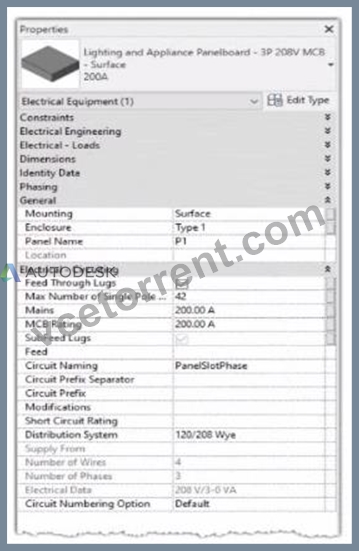
The Circuit Naming Scheme PanelSlolPhase. which defines the value of the Circuit Number parameter, is configured as follows: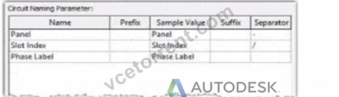
In electrical settings. Phase Labels have not been modified from the default "A." "B." and "C- The Circuit Number lot a single-pole circuit in the panelboard's first breaker position is----------(Enter the correct value into the field)
Answer:
Explanation:
See the explanation
Explanation:
The answer is P1/1/A
In Autodesk Revit Electrical Design, the Circuit Number for a branch circuit in a panelboard is automatically generated based on the Circuit Naming Scheme specified in the project's Electrical Settings. This naming scheme defines how each circuit is labeled by combining predefined fields such as Panel Name, Slot Index, and Phase Label.
From the exhibit, the Circuit Naming Parameter setup is configured as:
Name
Prefix
Sample Value
Suffix
Separator
Panel
Panel
Panel
-
"-"
Slot Index
Slot Index
Slot Index
-
"/"
Phase Label
Phase Label
Phase Label
-
-
The panelboard properties show that its Circuit Naming method is set to PanelSlotPhase, which means that Revit will generate circuit numbers using the following structure:
[Panel Name] - [Slot Index] / [Phase Label]
From the exhibit:
Panel Name: P1
Slot Index (Breaker Position): 1 (since the question refers to the first breaker position) Phase Label: A (default value for the first phase in a three-phase 120/208V Wye system) Therefore, the Circuit Number for a single-pole circuit in the first breaker slot will be:
✅ P1-1/A
This follows Revit's documented logic for circuit naming. According to the Autodesk Revit MEP User's Guide (Chapter 17 "Electrical Systems"):
"The circuit numbering format is controlled by the Electrical Settings > Circuit Naming template. The default scheme combines panel name, circuit number, and phase label, using the separators defined by the user." Furthermore, the Smithsonian Facilities Revit Template User's Guide confirms:
"In the default electrical configuration, circuit numbers use the format [Panel Name]-[Circuit Number]/[Phase], such as 'P1-1/A' for the first single-pole circuit on phase A." Hence, based on the provided configuration and standard electrical setup, the correct circuit number for the first single-pole breaker position in panelboard P1 is P1-1/A.
References:
Autodesk Revit MEP User's Guide - Chapter 17 "Electrical Systems," pp. 420-427 Smithsonian Facilities Revit Template User's Guide - Section 8.6 "Panel Schedules and Circuit Naming Schemes," p. 90 Autodesk Revit Electrical Design Essentials - "Circuit Naming Rules and Panel Configuration Standards"
NEW QUESTION # 24
Refer to exhibit.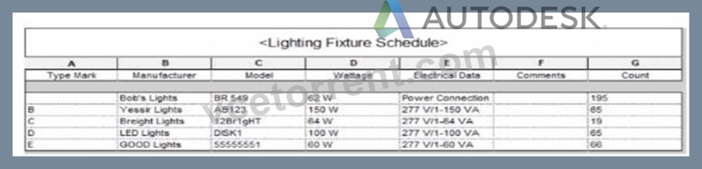
Which two actions were used to create this light fixture schedule? (Select two.)
- A. Sorted by instance and quantity.
- B. Sorted by type mark.
- C. Deselected Itemize every instance.
- D. Added both electrical and switch system settings.
- E. Filtered to only show lights that have a type mark value.
Answer: B,C
Explanation:
In the given Lighting Fixture Schedule, each row represents a lighting fixture type rather than individual instances, and the "Count" column summarizes how many fixtures of that type exist in the project. To achieve this layout in Revit, two specific actions must be performed in the Schedule Properties dialog:
Deselected "Itemize every instance."
The Revit documentation explains:
"Itemize every instance. This option displays all instances of an element in individual rows. If you clear this option, multiple instances collapse to the same row based on the sorting parameter. If you do not specify a sorting parameter, all instances collapse to one row." By deselecting this checkbox, Revit consolidates identical fixture instances of the same type into a single row - exactly as shown in the exhibit, where each "Type Mark" (A, B, C, etc.) appears once with a summarized Count.
Sorted by Type Mark.
On the same Sorting/Grouping tab, Revit allows users to organize the schedule by a specific field:
"On the Sorting/Grouping tab of the Schedule Properties dialog, you can specify sorting options for rows in a schedule... You can sort by any field in a schedule, except Count." In the example, fixtures are sorted alphabetically by their "Type Mark" (A through E). This ensures the grouped and counted results appear in order.
Other options-such as filtering by type mark or adding switch data-do not impact how instances collapse or group within the schedule.
NEW QUESTION # 25
Refer to exhibit.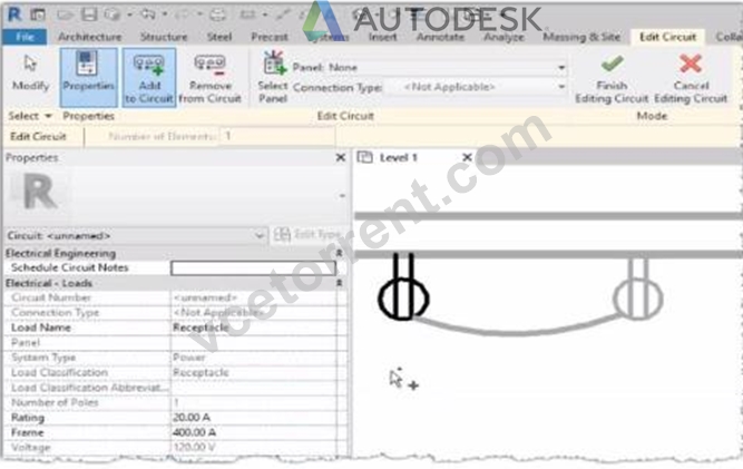
Why is one receptacle shown in full color (black) and one receptacle shown in halftone (gray)?
- A. The two receptacles are not on the some circuit.
- B. The two receptacles have different load classifications.
- C. The circuit's panelboard is not assigned.
- D. The wire connecting the two receptacles is not property attached
Answer: A
Explanation:
In Autodesk Revit MEP, when working with electrical circuits, Revit visually differentiates elements based on their circuit membership and active selection during the circuit editing process. In the Edit Circuit mode, the software highlights elements connected to the active circuit in full color (black), while other electrical devices not part of that same circuit appear in halftone (gray).
In the exhibit, one receptacle appears in black, while the other is shown in gray (halftone). This indicates that only one of the receptacles is currently included in the circuit being edited, while the other receptacle belongs to a different circuit or has not yet been assigned to any circuit.
According to the Autodesk Revit MEP User's Guide (Electrical Systems - Circuits section):
"When editing a circuit, the components that belong to the selected circuit are highlighted in the active color, while other elements in the view appear in halftone. Devices that are not on the same circuit will not be shown as connected or editable until added to the current circuit." Therefore:
The black receptacle is the one actively included in the selected circuit.
The gray (halftone) receptacle is not on the same circuit and thus not active for editing.
This visual cue is Revit's way of helping the designer distinguish between circuit connections when adding or managing electrical devices.
NEW QUESTION # 26
An electrical designer needs to add spaces to a model displaying the architectural room name and number. What should the designer do before creating the spaces?
- A. Select Room Bounding from the architectural link's type properties.
- B. Change the architectural model display settings to By Host View,
- C. Select Save Positions for the architectural links in the Manage Links dialog.
- D. Use Transfer Project Standards to Import rooms from the architectural model.
Answer: A
Explanation:
Before placing spaces in an MEP model that should reflect architectural room names and numbers, the linked architectural model must be set to Room Bounding. This ensures that Revit recognizes the architectural walls and room boundaries, allowing the spaces to reference and display room information correctly.
As the Revit MEP documentation explains:
"Turns on the Room Bounding parameter for the linked model. This step ensures that the Revit MEP project recognizes room-bounding elements in the Revit Architecture project."
"The spaces use the room boundaries defined by the Revit Architecture project." Additionally, the section Using Room Boundaries in a Linked Model details the procedure:
"In a plan view of the host project, select the linked model symbol → Click Modify | RVT Links tab ➤ Properties panel ➤ (Type Properties). In the Type Properties dialog, select Room Bounding." Once this setting is enabled, Revit MEP automatically detects the architectural rooms, enabling the designer to place spaces that inherit the architectural room name and number.
NEW QUESTION # 27
Refer to exhibit.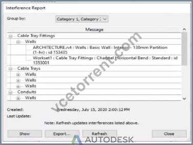
An electrical designer runs an interference check and reviews the Interference Report.
How can the designer select the cable tray fitting referenced in the interference to resolve the clash?
- A. Select the row with the cable tray fitting, click Show, and select the fitting.
- B. Click Export, expand Cable Tray Fittings, and select Channel Horizontal Bend: Standard.
- C. Double-click the fitting that appears in the list.
- D. Select the row with the cable tray fitting, and activate IDs of Selection.
Answer: A
Explanation:
When performing an Interference Check in Revit, the Interference Report dialog is generated. This report lists all interfering elements found. To select or locate a specific element-such as a cable tray fitting-the designer must use the Show command.
The official workflow from the Revit documentation clearly states:
"To see one of the elements that is intersected, select its name in the Interference Report dialog, and click Show. The current view displays the problem." This confirms that selecting the row that lists the interfering cable tray fitting and clicking Show will highlight and activate the view containing the clashing element-allowing it to be modified or moved to resolve the conflict.
This means the designer must:
Click the row containing the cable tray fitting in the Message list.
Click Show to highlight and locate it in the model view so the clash can be addressed directly.
This reference explicitly confirms that Show is the correct method to select the clashing cable tray fitting from the interference results in order to resolve the conflict.
NEW QUESTION # 28
Refer to exhibit.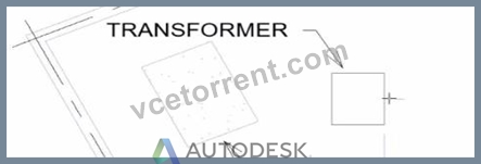
An electrical designer wants to place electrical equipment on the pad.
How should the component be aligned to the pad before placement?
- A. Start the Align tool. tab to select the object edge, and then select the equipment edge.
- B. Place the cursor over an edge of the object and then press Spacebar.
- C. Start the Align tool and select the edges to be aligned.
- D. Place the cursor anywhere over the object and then press Spacebar.
Answer: B
Explanation:
In Autodesk Revit, when placing electrical equipment such as transformers, disconnects, or switchboards onto a pad or foundation, precise alignment is essential for accurate coordination with architectural and structural elements. During component placement, Revit provides an intuitive way to align an object before final placement using the Spacebar in combination with the object's edges.
When the cursor is hovered over an edge of the component (not just anywhere on it) and the Spacebar is pressed, Revit cycles the component's orientation, rotating it 90 degrees around its insertion point each time. This technique allows the designer to visually align the equipment's orientation with the pad or architectural geometry before clicking to place it.
According to the Autodesk Revit MEP User's Guide under "Placing and Modifying Components":
"While placing a component, move the cursor over an edge and press the Spacebar to rotate the element incrementally. This method helps align electrical or mechanical equipment with nearby reference geometry before placement." This method is ideal for electrical designers positioning pad-mounted equipment, ensuring that components such as transformers or switchgear are oriented precisely to site geometry, conduit routes, or building walls.
NEW QUESTION # 29
An electrical designer receives an architectural model and links it into the electrical model.
The designer wants to use the Copy/Monitor tool to copy the exact electrical fixtures created by the architect.
The designer also wants the software to automatically detect new electrical fixtures added to the architectural model.
Select the correct coordination settings from the drop-down lists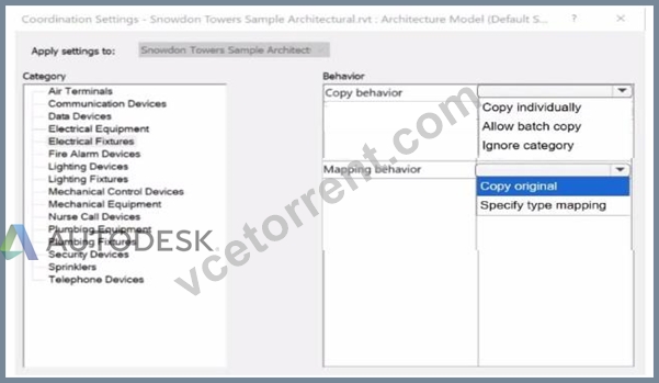
Answer:
Explanation: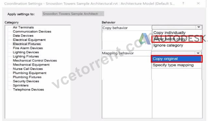
NEW QUESTION # 30
Refer to exhibit.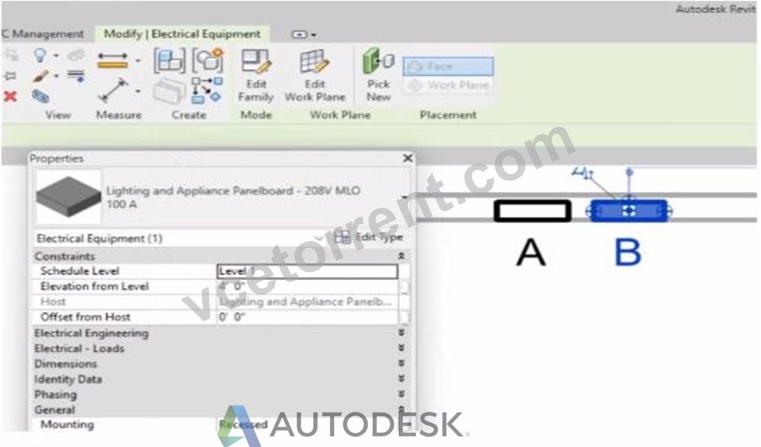
An electrical designer has accidentally hosted Panel B to Panel A. Select two ways the designer can correct hosting. (Select two.)
- A. Use the Pick New command in the Work Plane panel.
- B. Use the Edit Work Plane command
- C. Edit the Host value in the Properties palette.
- D. Use the Move command.
- E. Edit the Mounting value in the Properties palette.
Answer: A,B
Explanation:
In Autodesk Revit's Electrical discipline, when electrical components such as panelboards are hosted incorrectly (for example, Panel B hosted to Panel A instead of a wall or level), the hosting relationship must be corrected by reassigning the work plane or host. This is essential because hosted electrical elements depend on the geometry or level of their host for placement, alignment, and coordination.
According to the Revit MEP User's Guide (Chapter 45 "Work Planes and Element Hosting"):
"If a hosted element is placed incorrectly or the host has changed, use the Edit Work Plane or Pick New commands to redefine its host or work plane." Here's how these two tools apply:
Pick New (Option A)
Located under the Work Plane panel on the Modify tab, this command allows you to select a new face or host (e.g., a wall, ceiling, or floor) for the existing component. It effectively reassigns the element's host without deleting or recreating the element.
"Use Pick New to specify a different face or surface as the host for a component that was incorrectly placed."
Edit Work Plane (Option E)
This command lets the designer redefine the reference level or named work plane to which an element is associated. For hosted electrical equipment (like lighting or panels), this ensures the object references the correct structural or architectural surface.
"To correct hosting errors, open Edit Work Plane from the Modify tab, and assign a new named plane, level, or face." Incorrect Options Explanation:
B . Edit Mounting value - changes only how the panel is mounted (e.g., recessed or surface), not the host itself.
C . Move command - repositions the element but does not change the hosting relationship.
D . Edit Host value - the "Host" parameter is read-only; it cannot be edited directly.
Thus, the correct methods to rehost Panel B from Panel A to the correct wall or work plane are through Pick New and Edit Work Plane, ensuring proper association and maintaining system connectivity.
References:
Autodesk Revit MEP User's Guide - Chapter 45 "Work Planes and Hosting," pp. 1068-1072 Smithsonian Facilities Revit Template User's Guide - Section 6.2.3 "Complex Geometry and Multiple Parametric Relationships," p. 57 Autodesk Revit Electrical Design Essentials - "Rehosting Electrical Equipment and Devices"
NEW QUESTION # 31
Refer to exhibit.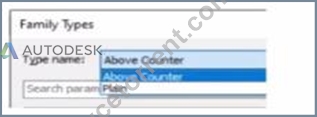
A family in a project contains the following types:
The following edits are made in the Family Editor and loaded into the project:
1. The type Plain is renamed to Standard
2 A new type is added named GFCI
Which types does this family now have in the project?
1. The type Plain is renamed to Standard
- A. Above Counter. GFCI. Plain. Standard
- B. Above Counter. Plain. Standard
- C. Above Counter. GFCI. Standard
- D. Above Counter. Standard
Answer: C
Explanation:
In Revit, when editing a family in the Family Editor and reloading it into a project, Revit handles type changes using specific update rules. Types that are renamed overwrite their earlier version in the project because they retain the same internal type ID. Types that are added to the family also appear in the project once reloaded.
Initially, the family contains two types:
Above Counter
Plain
The changes made in the Family Editor are:
Rename Plain → Standard
Add a new type named GFCI
According to documented Revit behavior for type updates:
"When a family is reloaded into the project, any renamed family type replaces its previous version while maintaining its parameter assignments. Newly created types are added as additional family types available for placement within the project." Therefore:
Plain no longer exists because it was renamed
Standard now exists in its place
GFCI is added as a new family type
Above Counter remains unchanged
Thus, the family in the project now contains:
✅ Above Counter
✅ GFCI
✅ Standard
This matches answer choice:
B). Above Counter, GFCI, Standard
NEW QUESTION # 32
An electrical designer needs to add spaces to a model displaying the architectural room name and number. What should the designer do before creating the spaces?
- A. Select Room Bounding from the architectural link's type properties.
- B. Change the architectural model display settings to By Host View,
- C. Select Save Positions for the architectural links in the Manage Links dialog.
- D. Use Transfer Project Standards to Import rooms from the architectural model.
Answer: A
Explanation:
Before placing spaces in an MEP model that should reflect architectural room names and numbers, the linked architectural model must be set to Room Bounding. This ensures that Revit recognizes the architectural walls and room boundaries, allowing the spaces to reference and display room information correctly.
As the Revit MEP documentation explains:
"Turns on the Room Bounding parameter for the linked model. This step ensures that the Revit MEP project recognizes room-bounding elements in the Revit Architecture project."
"The spaces use the room boundaries defined by the Revit Architecture project." Additionally, the section Using Room Boundaries in a Linked Model details the procedure:
"In a plan view of the host project, select the linked model symbol → Click Modify | RVT Links tab ➤ Properties panel ➤ (Type Properties). In the Type Properties dialog, select Room Bounding." Once this setting is enabled, Revit MEP automatically detects the architectural rooms, enabling the designer to place spaces that inherit the architectural room name and number.
NEW QUESTION # 33
Refer to exhibit.
(The Image is presented in Imperial units: 1 In = 25 mm [Metric units rounded).)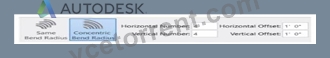
What is the electrical designer trying to do as shown in the exhibit?
- A. Add Cable Tray
- B. Place Multiple Pipe
- C. Place Parallel Conduits
- D. Array Conduit
Answer: C
Explanation:
The exhibit shown in the image is taken directly from the Revit MEP Electrical Systems workspace, specifically from the Parallel Conduits command interface. This dialog box appears when the designer activates the Place Parallel Conduits tool in the Systems tab → Electrical panel → Conduit dropdown → Parallel Conduits.
In this interface, the designer can specify:
Horizontal Number / Offset - defines how many conduits will be created horizontally and their spacing.
Vertical Number / Offset - defines how many conduits will be created vertically and their spacing.
Bend Radius Options:
Same Bend Radius - all conduits use identical bend radii.
Concentric Bend Radius - conduits bend concentrically around a common center point.
According to Autodesk's Revit MEP 2011 User's Guide (Chapter 18, Electrical Systems - Conduit Layout):
"The Parallel Conduits tool allows you to create multiple conduits side-by-side at the same time.
You can specify the number of conduits horizontally and vertically, as well as the offset between them.
You can also define whether bends have the same bend radius or concentric bend radii."
- Revit MEP User's Guide, Electrical Systems, Section: Conduit Layout
This tool is used when electrical designers need to route groups of conduits that run in parallel-such as power and data conduits running between panels or equipment racks.
The Concentric Bend Radius option (as shown in the exhibit) ensures all conduit bends share a common center, which is critical for maintaining uniformity in conduit sweeps and avoiding clashes during coordination.
Therefore:
A . Add Cable Tray - incorrect; the cable tray tool is separate and does not use bend radius options.
C . Array Conduit - incorrect; arraying is a different geometric function not specific to conduit routing.
D . Place Multiple Pipe - incorrect; applies to mechanical piping systems, not electrical conduits.
The display of Concentric Bend Radius, Horizontal Number, Vertical Number, and Offset confirms that the designer is using the Parallel Conduit placement tool.
Verified Reference Extracts from Revit Electrical Design Documentation:
Autodesk Revit MEP User's Guide (2011) - Electrical Systems → Conduit Layout → "Parallel Conduits Tool" description.
Autodesk Revit MEP Training Curriculum - Electrical Module, Exercise 6.3 "Placing Parallel Conduits," which illustrates the same interface for bend radius configuration.
NEW QUESTION # 34
An electrical designer has noticed lighting fixtures present in an architectural linked model. Which tool should be used to place an instance of those fixtures in the current electrical model while maintaining the position from the architectural model?
- A. Reload Latest
- B. Copy/Monitor
- C. Reconcile Hosting
- D. Coordination Review
Answer: B
Explanation:
When lighting fixtures placed in an architectural linked model need to be replicated in the electrical model while maintaining their exact positions, the correct tool is Copy/Monitor.
This Revit feature allows the electrical designer to copy elements-like lighting fixtures-from a linked model into their project, while establishing a monitoring relationship between the original (architectural) and copied (electrical) instances.
From the Autodesk Revit MEP User's Guide - Chapter 55 "Multi-Discipline Coordination" (pages 1349-1357):
"Use the Copy/Monitor tool to copy MEP fixtures from an architectural model into an MEP project, and monitor them for changes." (Revit MEP User's Guide, p. 1350)
"To copy fixtures from a linked model:
Click Collaborate tab ➤ Coordinate panel ➤ Copy/Monitor ➤ Select Link.
Select the linked architectural model in the drawing area.
Click Copy and select the lighting fixtures to copy.
Click Finish.
Revit MEP copies the fixtures to the current project and establishes monitoring relationships."* (Revit MEP User's Guide, p. 1356) Behavior and Benefits:
The copied lighting fixtures maintain the same location, orientation, and type mapping as in the linked model.
Any changes (move, delete, or modify) made by the architect in the linked model will trigger a coordination review in the electrical model.
This ensures accurate positioning and easy coordination between disciplines.
"When you select a copied fixture in the current project, the monitor icon displays next to the fixture, indicating that it has a relationship with the original fixture in the linked model." (Revit MEP User's Guide, p. 1357)
"If copied fixtures are moved, changed, or deleted in the linked model, Revit MEP notifies the engineers of the changes during Coordination Review." (Revit MEP User's Guide, p. 1357)
NEW QUESTION # 35
Refer to exhibit.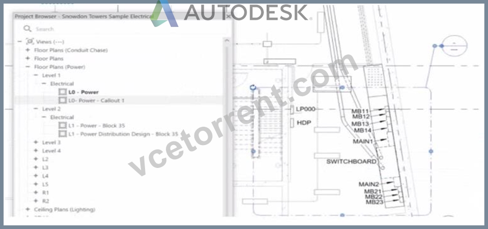
- A. Select the callout and choose a detail view under Reference Other View.
- B. Delete the existing callout and create a new one with the correct type.
- C. Open the callout view from the Project Browser and change its type.
- D. Select the callout and change its type from the Type Selector.
Answer: A
Explanation:
In Autodesk Revit, when an electrical designer creates a callout view, the software automatically generates a new dependent or independent view based on the selected callout type. However, if a callout is accidentally linked to the wrong or redundant view, the designer can easily reassign it to another existing view without recreating the callout. This can be done using the Reference Other View property in the Properties palette.
According to the Revit MEP User's Guide (Chapter 47 "Views and Callouts"):
"To link a callout to an existing view rather than creating a new one, select the callout, and under the properties for that element, use Reference Other View to specify the desired target view." This means that when the designer selects the callout (in this case, shown as "L0 - Power - Callout 1" in the Project Browser), they can modify the Reference Other View setting from the Properties palette to point to a different, pre-existing detail view or callout view-for example, one showing an enlarged power distribution layout or switchboard detail.
This is the most efficient workflow because:
It avoids recreating or redrawing the callout (unlike Option C).
It preserves all annotation and sheet referencing data.
It ensures alignment and consistency across sheet references.
The Smithsonian Facilities Revit Template User's Guide reinforces this standard Revit practice:
"When a view reference or callout is incorrectly associated, use the Reference Other View property to redirect the annotation to an existing detail or dependent view." Why the Other Options Are Incorrect:
B . Change its type from the Type Selector: Callout types control annotation style (not the referenced view).
C . Delete and recreate: This is unnecessary and inefficient.
D . Open the callout view and change its type: Callout type cannot be changed directly once created; it's controlled by view properties.
Therefore, the correct and Revit-recommended approach is Option A: Select the callout and choose a detail view under Reference Other View.
References:
Autodesk Revit MEP User's Guide - Chapter 47 "Views and Callouts," pp. 1092-1097 Smithsonian Facilities Revit Template User's Guide - Section 2.8.1 "View Types and Templates," pp. 29-31 Autodesk Revit Electrical Design Essentials - "Callouts, Detail Views, and Referencing Workflows"
NEW QUESTION # 36
Refer to exhibits.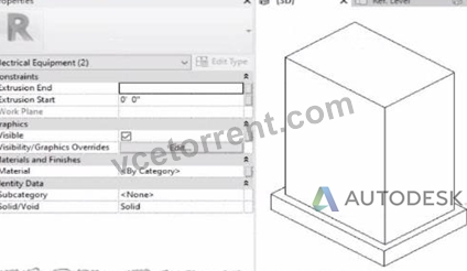
When loaded into a project, the family displays as below in plan view.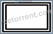
The electrical designer is satisfied with the line color and weight of the transformer because it matches all other electrical equipment in the project. However, the designer wants the housekeeping pad to display with different line properties as shown below.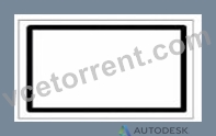
How can this be achieved?
An electrical designer creates a simple family of a transformer with a concrete housekeeping pad using two rectangular extrusions. Both extrusions and their properties within the family editor are shown.
- A. Within the family editor, create a new object style subcategory with the desired properties. Assign that subcategory to the housekeeping pad object.
- B. Within the family editor, right-click the housekeeping pad object and select Visibility from the context menu. Edit the line properties as desired.
- C. Within the project, right-click and select Override Graphics in View from the context menu. Edit the line properties as desired.
- D. Within the family editor, select the housekeeping pod object and change it from a solid to a void.
Answer: A
Explanation:
In Autodesk Revit Electrical Design, when customizing a family-such as a transformer with a housekeeping pad-each element within the family can have its own subcategory under the parent category (in this case, Electrical Equipment). Subcategories are critical for controlling line weight, color, and material properties independently in project views and visibility settings.
The issue described is that the transformer and its concrete pad currently share the same default category (Electrical Equipment) and therefore use identical line weights and colors in plan view. The designer wants the housekeeping pad to display differently - for example, with a lighter or dashed outline.
According to the Autodesk Revit MEP User's Guide (Chapter: Creating and Editing Families):
"To control the visibility or graphical appearance of individual components within a family, create a new Object Styles subcategory under the parent category. You can then assign any solid or void geometry in the family to that subcategory. When loaded into a project, the subcategory can be independently controlled through Visibility/Graphics (VG) settings." This is the exact and recommended workflow for differentiating line appearances between elements in the same family.
Steps to achieve this:
In the Family Editor, open Manage tab ➤ Object Styles.
Under the Model Objects tab, click New to create a new subcategory (e.g., "Housekeeping Pad").
Set the desired line weight, color, or material properties.
Select the housekeeping pad extrusion in the model.
In the Properties palette, under Identity Data → Subcategory, choose Housekeeping Pad.
Reload the family into the project.
You can now modify or control its visibility independently in project views.
Why the other options are incorrect:
A . Change to void: A void removes geometry, not graphical appearance.
B . Override Graphics in View: Applies only in a single view, not globally across the project.
D . Visibility from context menu: Controls whether the object is visible, not its line properties.
Thus, the most efficient, parametric, and Revit-standard method is to use subcategories within the family to apply distinct graphical controls.
References:
Autodesk Revit MEP 2011 User's Guide, Chapter 53: Creating Families - Managing Object Styles, pp. 1248-1251.
Autodesk Revit Architecture 2020 Help, "Assigning Geometry to Subcategories in Families." Smithsonian Facilities Revit Template User's Guide (2021), Section 8.4.1 - Electrical Equipment Family Standards and Subcategories.
NEW QUESTION # 37
Refer to exhibit.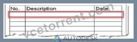
An electrical designer is issuing several sheets and wants 'Issued for Bid" to appear in the revision schedule of the title block. Drag and drop into the correct order to indicate how this can be accomplished to only the sheets that are being issued.
Answer:
Explanation: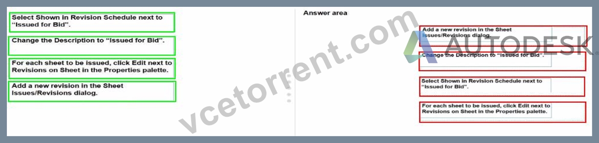
NEW QUESTION # 38
......
Dumps Brief Outline Of The RVT_ELEC_01101 Exam: https://www.vcetorrent.com/RVT_ELEC_01101-valid-vce-torrent.html
RVT_ELEC_01101 Training & Certification Get Latest Autodesk Certified Professional: https://drive.google.com/open?id=1FS5Njb779CFL7FpdB4xISK5nrd2wmapO